
Every Psion collector knows that the parts for Psion 5MX are scarce nowadays. The serial cable is no exception. The only current source is Psionex, but it can cost more than $50 with shipping to US. Too expensive for just a used cable.
Recently I asked about this on Reddit, and a kind user suggested me to look into some PCMCIA dongles, as they seems to have similar connectors. I did that and happily discovered it is possible to make a Psion serial cable out of PCMCIA dongles, at a relatively low cost, and with a good-looking finish. Let me document the process here.
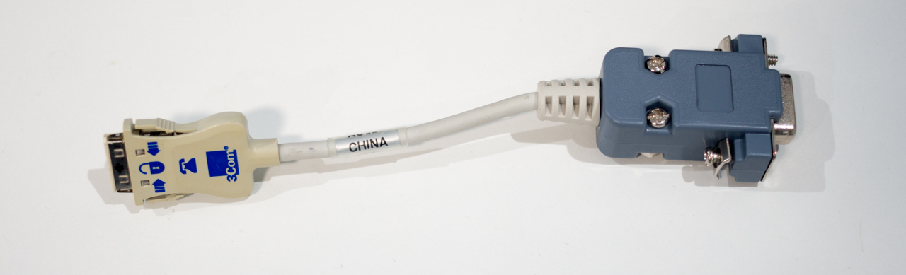
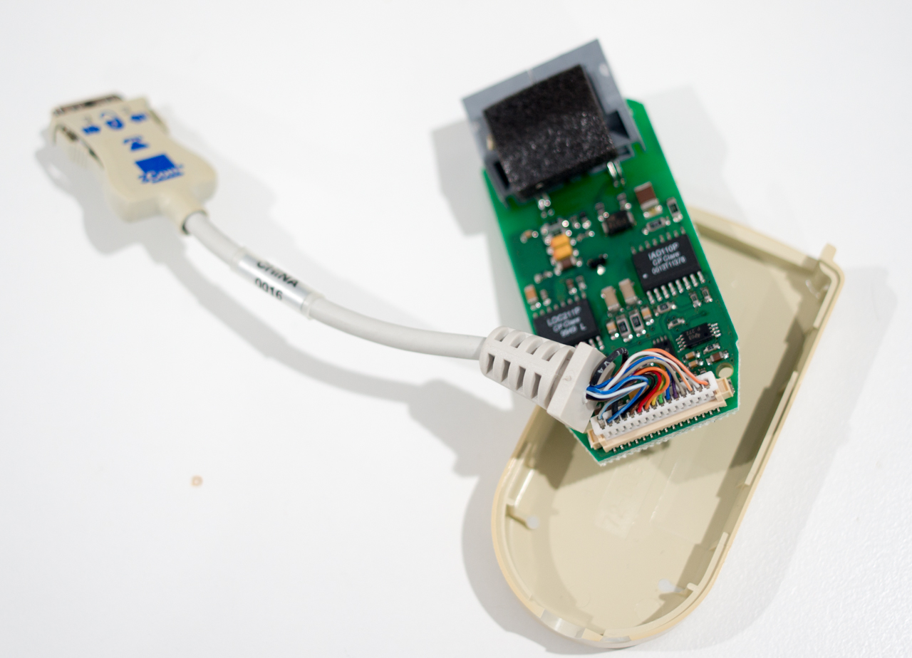
The original Psion cable used a connector from Honda Tsushin Kogyo, Part No. RMC-E15F4S-LC5-MC1BK. It is no longer being made, and there are no distributors selling this connector anymore. However, many PCMCIA Ethernet and Modem card used dongle cables that have similar connectors (15 pin, 0.8mm pitch), but not exactly the same part. I find out 3Com PCMCIA dongles were the easiest to get and has a great hope to fit. So I bought one from eBay for under $10 shipped.
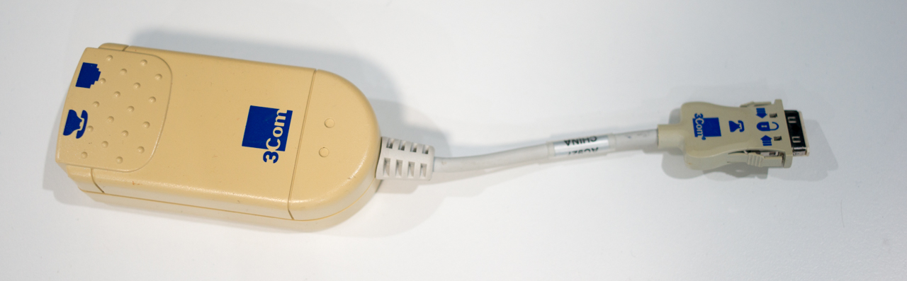
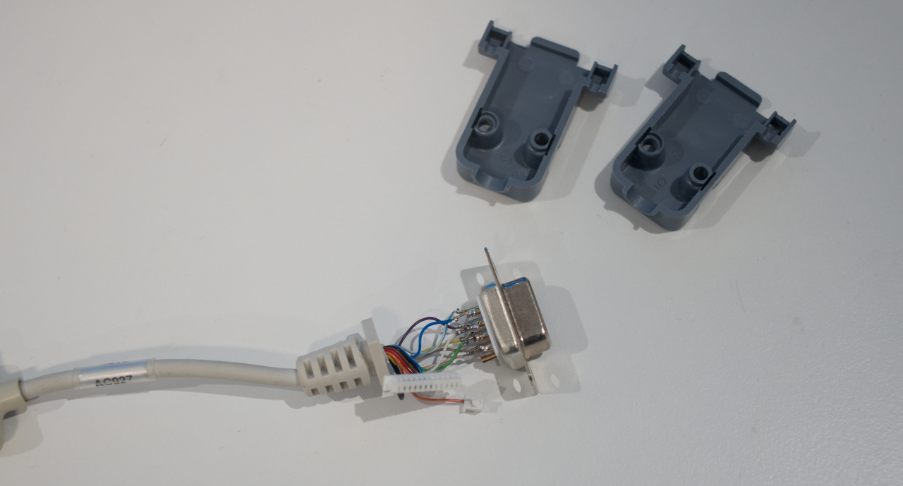
The dongle part No. is 3CCFEM556-DAA-CBL, it is a dongle for 3Com’s modem card (which is useless today, as Wifi-232 modems are very common. So I have no burden to repurpose one). There are other 3Com cables that has this connector for their other modem or Ethernet cards, but this particular one has one advantage: the whole 15 wires are available from the connector’s 15 pins, while other 3Com dongles may only partially populate the wires (I don’t know, I haven’t tested many). We need this because it is not easy to disassemble from the connector side. By using this one, I can just solder a RS-232 female header to the other end. I bought one header+plastic housing from Aliexpress for $1, this is a pretty standard part.
The pinout of the Psion serial cable is documented at https://www.thomasdoppler.com/_pocketreader/docs/psion_cable.gif and https://wookware.org/psion.html. I’ll write the wiring diagram here. The wiring assumes you want to make a female cable which puts the Psion as the DCE role (just like the OEM Psion cable). This is essentially a null-modem cable. If you want a male header as DTE role, you should wire it as straight through.
| DE9 pin No. | DE9 pin name | signal direction | Psion pin No. | Psion pin name |
| 1 | DCD | not connected | ||
| 2 | RXD | -> | 4 | TXD |
| 3 | TXD | <- | 8 | RXD |
| 4 | DTR | -> | 5 | DSR |
| 5 | GND | 15 | GND | |
| 6 | DSR | <- | 3 | DTR |
| 7 | RTS | -> | 7 | CTS |
| 8 | CTS | <- | 2 | RTS |
| 9 | RI | -> | 6 | DCD |
The steps to make it:
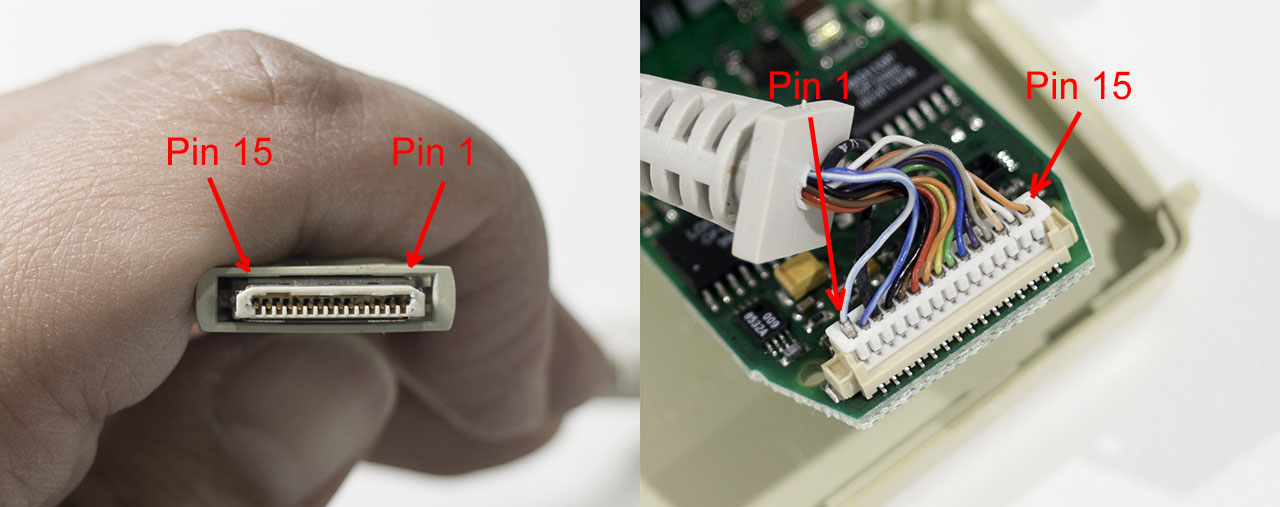
- Pry open the dongle case, detach the cable from its PCB.
- (Optional) use a multi-meter with needle-tip probe to test the continuity of wire 2,3,4,5,6,7,8,15. If any of these wires are broken, then it is not good. You should return the dongle 🙂 . At a bare minimum, wire 4,8, 15 needs to be good.
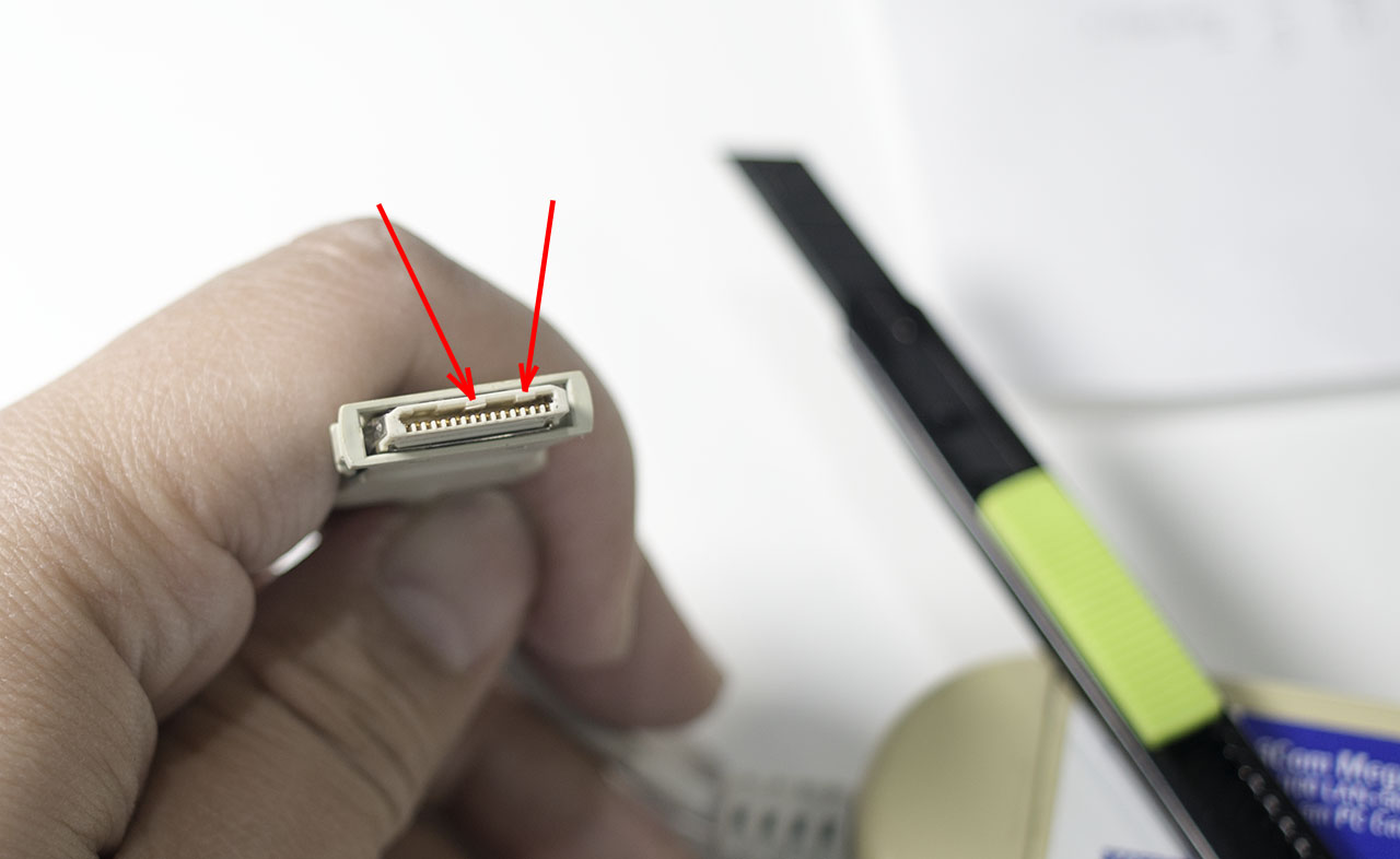
- Use a thin utility knife to cut the two notches off inside the male connector, so it fits better. Use a needle to clean out all the plastic debris. Be careful not to damage any pins.
- pop each wire from the plastic connector housing, one wire at a time so you don’t lose track of the order, solder each wire to the female RS232 header according to the wiring diagram above.
- (Optional) once you’ve done all 8 wires, use a multi-meter to test the continuity again.
- Cut the size of the square part of the strain relief, so it can fit in the female header’s plastic housing. Also cut the plastic housing’s “tube” part, otherwise the strain relief won’t put in.
- Put on the plastic housing and secure the screws. You can leave the rest of the wires and the connector housing inside, or you can add some insulation to them.
Now you can test the cable on the Psion, e.g. by using the Comms app to communicate with your PC’s RS232 port.
I hope this method can help. It is not ideal to rely on another old part, but hopefully this provides an alternate when the buying options are limited. You are welcome to experiment with other PCMCIA dongles, too.